Please read the following instructions before starting.
Installation Timing: 45 minutes for a first timer For Questions & Support: Call the Compactor Monitoring Service Operations Department at 1-800-275-6646. Pro Tip: Carefully read these instructions before going to the job site.
Installation Overview
Installation of the CMS Monitor 4.0 consists of:
connecting one hydraulic line from the compactor power pack to the monitor,
wiring into the control panel for power, and
vertically mounting via magnets to a nearby stationary metal surface.
With Monitor 4.0, there is no need to open the enclosure.
Tools Needed to Make the Job Easy
Pipe Wrenches for Hose Fittings And an extension “cheater” pipe.
Open-End Wrench Set Down to 1 3/8”, long handle, plus a smaller set down to 7/16” or adjustable crescent wrenches.
Teflon Tape For pipe thread fittings only. NOT for JIC fittings.
Flashlight & Rag
Standard Materials Supplied With Monitor:
Fittings (One Each)
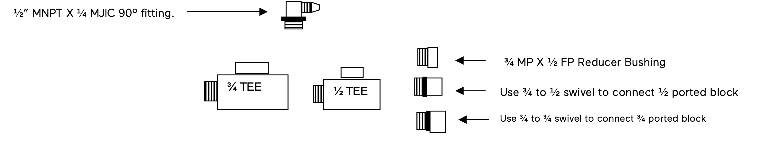
1404-08-08-08 - 1/2 MNPT X 1/2 FNPT Swivel
1404-12-12 - 3/4 MNPT X 3/4 FNPT Swivel
2501-04-08 FG - 1/2 MNPT X 1/4 FJIC 90 Degree
5602-12-12-12 - 3/4 MNPT X FNPT X FNPT Street Tee
5602- 08-08-08 - 1/2 Steel MP X FP x FP Street Tee
54061-08 - 3/4 MP x 1/2 FP Reducer Bushing
Hose 2SN04-2WB-04FJX - 1/4" x 6 Ft., 2SN, FJIC each end
Wiring 6’ Wiring Pigtail Type SOOW Cable
Installation Sequence
Step 1: Attach the monitor
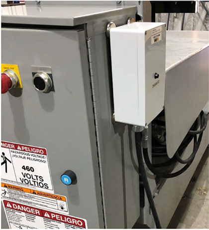
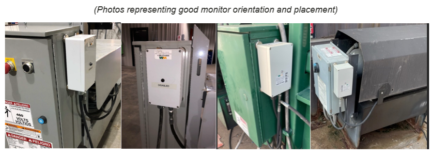
Mount monitor vertically via magnetic feet on the side of the main panel. This will make for easy connection of the wiring to the power pack.
Do not mount the monitor to any part of the compactor that is removed when the compactor is emptied.
Monitor Installation Completion Form
You must submit the monitor installation form to receive payment.
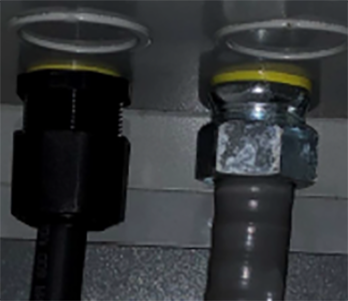
Connect the supplied 6 ft. 1/4” hydraulic hose to the bulkhead fitting located at the bottom of the monitor.
To prevent loosening and twisting of the transducer and cable, do not wrench on the bulkhead fitting nut when tightening the hydraulic hose connection.
Step 3: Connect the hydraulic line to the compactor
The extend hose (ram moving forward) is one of the two hydraulic hoses that connect the ported block to the ram cylinder. Incorrect hydraulic hose connection is the most common cause of a failed installation. To avoid extra trips to the site and several weeks of delay, the following methods outline how to identify the extend hose (ram moving forward):
It is connected to the REAR of the ram cylinder away from the rod end of the cylinder. This is a positive identification. Very often it is not visible without removing an access panel on the ram housing. Sometimes it can be seen from underneath the ram housing compartment. This is where you will need a light.
It vibrates more strongly and is stiffer than the other hose when the ram is traveling forward to compress trash. You must be able to see that the ram is moving FORWARD, as some compactors start in the retract stroke.
It may have a pressure gauge attached to it. This is a valid guide only if the gauge is between the ported block and the ram cylinder.
Most compactors use 1/2” hoses to run between the power pack and the ram cylinder located inside the compactor ram housing. Some compactors use 3/4” or even 1” hose. Disconnect the extend hose at the ported block on the power pack. Attach the appropriate size Tee then attach the Tee and hose to the ported block using the proper size swivel union to match the thread on the connection at the ported block. Attach the 1/4” JIC 90º fitting into the Tee and connect the supplied hose to the 1/4” JIC 90º fitting.
Do not use teflon tape on the JIC fittings.
Bleed the air out of the line by loosening the hose connection at the monitor and starting the compactor momentarily (about 1/2 second). You should have a rag or paper towel wrapped around the loosened connection to catch the excess fluid. Another method of bleeding the air from the system can be done by inserting the monitor end of the hose into the hydraulic oil reservoir and running the compactor momentarily. Be careful! The hydraulic fluid will come quickly and with some force.
Step 4: Connect the wiring
Make sure the power is cut off to the compactor at the electrical disconnect box! Use a lockout/tagout to make sure power is not restored accidentally.
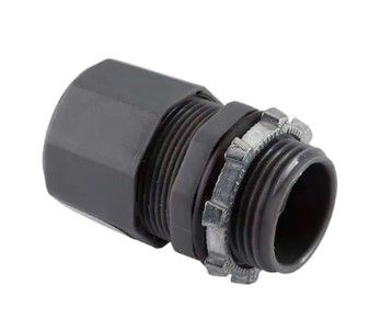
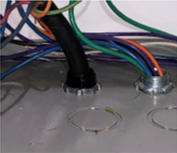
Punch a hole in the main panel for the SO Cord to go through. Using an SO cord connector (not provided), insert SO cord so that you have about 12 inches of it on the inside of the panel. Then tighten SO cord connector.
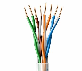
Trim off the outer jacket of the SO cord to expose the 7 different colored wires (white, black, green, red, blue, orange and white/black stripe). You will only be using 6 of them. The white/black stripe wire will not be used.
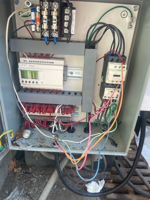
Proceed using the following connections:
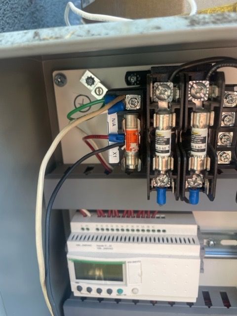
Connect black wire to 120V screw on transformer.
Connect white wire to neutral on transformer.
Connect green wire to ground screw on electrical panel.
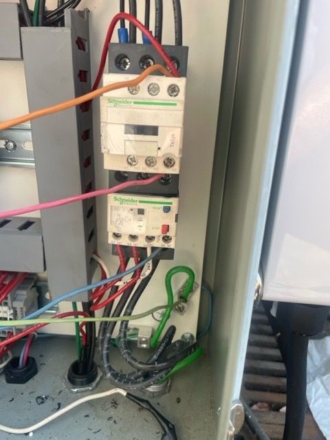
Connect orange wire to A1 on the motor starter. Make sure motor starter coil is 120V. If not 120V do not proceed with installation. Extra parts will be needed to complete the installation.
Remove the wire going between 96 on overload and A2 on motor starter.
Connect red wire to A2 on motor starter.
Connect blue wire to 96 on overload.
Wiring example photos:
Step 5: Final Check
After all wiring has been connected, follow the instructions below and pay close attention to the red LED on the center of the monitor lid, looking for the following light sequences to occur.
Turn the compactor power on - Once the monitor is energized, the redLED will blink slowly indicating self-diagnostic checks of all internal sub systems and server connections. As soon as all checks are successfully completed, the red LED should turn off.
Cycle the compactor - While running, the red LED will start blinking fast confirming motor activity has been detected. If the red LED does not blink, recheck your electrical and hydraulic connections.
Wait for Cycle completion - Once the compactor cycle stops, the red LED should turn off and remain off and be ready to transmit PSI and cycle data wirelessly.
Check all hydraulic fittings for leaks, including the transducer connection from the monitor enclosure. Check the monitor cover to make sure it is secured and sealed tightly with the four screws on the corners of the box. Double check to make sure the monitor has been mounted in a spot where it will not be disturbed or removed easily. Make sure the hydraulic hose connection is not leaking.
Step 6: Confirm completion of installation
IMPORTANT! Upon completing the monitor installation, please carefully read the following instructions to provide the necessary information regarding your compactor monitor before leaving the site.
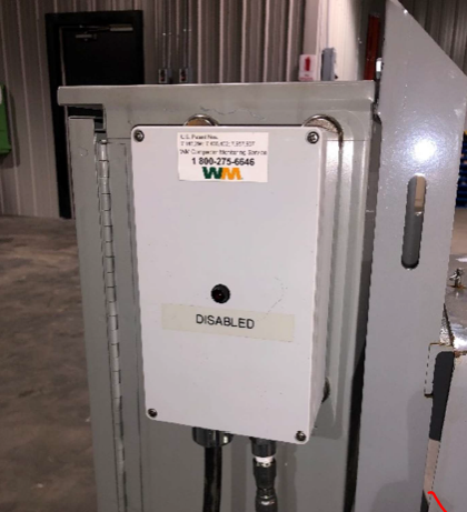
As seen in the pictures below, take photos of the completed installation showing where the monitor was mounted, where the hydraulic connection was made and the front of the monitor showing the label with the monitor's serial number.